愛媛大学 理工学研究科
Research Projects
River levee: Liquefaction of soil inside levees
1. Seismic damage to river levees
2. Liquefaction of levee
2.1 Some case histories
2.2 Damage mechanism
2.3 Assessment method
2.4 Countermeasure
3. References
Seismic damage to river levees
It has reported that large settlement of dikes during past earthquakes was more or less associated with liquefaction of foundation soils. Shaking table tests and centrifuge tests on embankments resting on loose saturated sand also showed that the major cause of the dike settlement was the lateral deformation of liquefied soil beneath dikes away from the embankment centerline.(*1)。Major earthquakes after the World War II including Niigata (1964), Nihonkai Chubu (1983) and Hyogoken-nambu (1995) caused significant liquefaction-induced damage to many river dikes. The underlying mechanism of the damage was believed to be the liquefaction of foundation soils, remedial countermeasure techniques have been developed and applied in practice for existing levees after the Kobe earthquake.
Meanwhile, in 1993, the Kushiro-oki earthquake hit the northern part of
Japan and the Kushiro river levees were se-verely damaged. The incident
attracted attention of engineers since damaged levees were underlain by
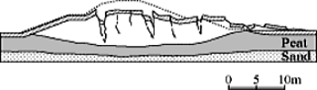
a non-liquefiable peat deposit. It was presumed that the surface of the
highly compressible and less permeable peat deposits (peculiar to some
Hokkaido areas) below the levees had sub-sided in a concave shape, creating
saturated zone in the levees, and the submerged zone in the levee liquefied
during the earthquake(*2)。More recently, more than 2000 river levees were damaged by the 2011 off
the Pacific Coast of Toho-ku Earthquake (River Bureau, Ministry of Land,
Infrastructure and Transport, 2011) and a considerable number of levees
failed in this mechanism.
(*1)River levees in Japan resting on liquefiable foundation soils often causes large crest due to earthquakes, with the settlement being as large as 75% of levee height. On the other hand, for river levees on foundation soil without any liquefiable soil layers, observed maximum crest settlement during past earthquakes was about 15% of levee height.
(*2)It was presumed that the surface of the highly compressible and less permeable peat deposits below the levees had subsided in a concave shape, creating saturated zone in the levees, and the levee soil in the saturated zone liquefied and caused large deformation to the levee during the earthquake (Sasaki et al., 1995).
(*3)Soft clayey soils prevail ground surface in Tohoku area.
Liquefaction of soil inside levees
Few research works had been devoted to issues regarding liquefaction of soil inside levees.
Some case histories
1993 Kushiro-oki Earthquake
From the investigation for damage detection, the following characteristics
of severely damaged sections were found.
(a) There was comparatively thick peat layer at top of foundation ground of the dike.
(b) The height of the damaged dike was comparatively high.
(c) Construction material for dike was sandy soil.
(d) Traces of sand boils were found at berm or near the toe of slope, however
numbers of sand boils were not great.
 These characteristics of the damaged sections resembled the characteristics
reported for the damage by the 1968 Tokachi-oki earthquake. It should also
be noted that the boundary between the dike bottom and the surface of peat
layer is descending due to consolidation of peat layer. The peat in this
area usually has 800-1000 % of water content and has large compressibility
coefficient. Settlement of the top of the peat layer coincides well with
the compression of the peat layer by the weight of dike.
These characteristics of the damaged sections resembled the characteristics
reported for the damage by the 1968 Tokachi-oki earthquake. It should also
be noted that the boundary between the dike bottom and the surface of peat
layer is descending due to consolidation of peat layer. The peat in this
area usually has 800-1000 % of water content and has large compressibility
coefficient. Settlement of the top of the peat layer coincides well with
the compression of the peat layer by the weight of dike.
1993 (JGS(2001):Case Histories of Post-Liquefaction Remediation).
2011 Off the Pacific Coast of Tohoku Earthquake
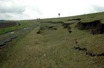
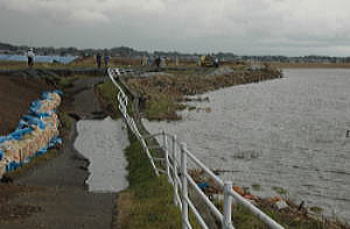
Tone river levee with slope slid down Heavily deformed and subsided Hinuma river levee
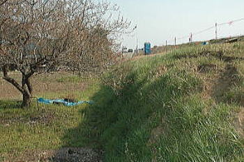
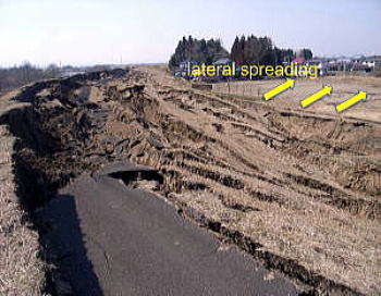
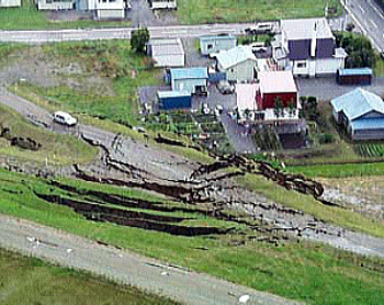
arise river levee at Shimo-nananome district: liquefied levees tend to spread laterally, with convex toes and significant longitudinal cracks and fissures, occasionally with sand boils found in the cracks.
2003 Tokachi-oki Earthquake
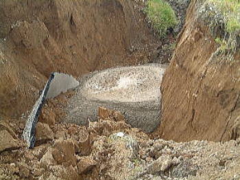
Tokachi river levee also damaged in the mechanism of liquefaction of levee soil, with significant longitudinal cracks and sand volcanos in the cracks.
Damage mechanism
Mechanism to cause damage to river levee due to the liquefaction of levee soils can be summarized as follows;
- Construction of levee on a foundation ground with highly compressive and less permeable soils causes consolidation settlement and the base of levee becomes curvature with concave shape.
- Rain and ground water infiltrated through the levee is accumulated in the bowl and forms saturated zone in the levee.
- The soil in the saturated zone liquefies during an earthquake and causes significant deformation to the levee
However, detailed mechanisms in these process are still not very clear,
including height of water table in the levee and its seasonal variation.
There may be a due question that “is it possible for a thin liquefied layer
to largely deform a levee?” We do not have any clear answers to the questions.
A series of well-designed centrifuge tests were conducted to look into
more in detail the mechanisms. (*3)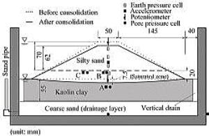
Okamura & Tamamura (2011),Okamura, Tamamura & Yamamoto (2012)
In this study, centrifuge tests were conducted to investigate the seismic
stability of a partly saturated embankment with and without the influence
of deformation before shaking. The experimental data also provides useful
bases for calibration of numerical analysis and for verifying design guidelines.
Two aspects as the underlying mechanism are focused on in this study; one
is thickness of the saturated zone. A possibility of liquefaction of a
thin saturated zone with a thickness of only about one meter is experimentally
 investigated. The other is the effects of deformation and associated stress
change of the embankment due to foundation settlement on the seismic stability
of embankment. Seismic responses of the embankment with and without imposed
deformation due to consolidation of the foundation soil are compared.
investigated. The other is the effects of deformation and associated stress
change of the embankment due to foundation settlement on the seismic stability
of embankment. Seismic responses of the embankment with and without imposed
deformation due to consolidation of the foundation soil are compared.
Model levees were built on such foundation soils as soft clay, stiff clay
or dense sand and consolidate in a centrifuge at 40g. For cases of embankments
on clay, it was observed that horizontal stresses were apparently lower
especially at lower part of the embankments, if 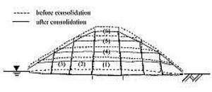 the embankment underwent subsidence due to consolidation of foundation
clay. For the case of consolidation settlement as high as 13% the embankment
height, the embankment soil at around bottom center apparently loosened
with the volumetric strain of -3%.
the embankment underwent subsidence due to consolidation of foundation
clay. For the case of consolidation settlement as high as 13% the embankment
height, the embankment soil at around bottom center apparently loosened
with the volumetric strain of -3%.
It was found that reduction of stresses in embankments, degradation of
soil density and an increase in thickness of saturated zone in embankments,
all due to subsidence of the embankment are surmised as underlying  mechanisms. Horizontal base shaking was applied to the models. The rate
of generation of excess pore pressures in the saturated zone was higher
and crest settlement was greater for the embankment subjected to large
consolidation settlement. This is believed to be due to the combined effect
of the stress reduction and the degradation of soil density, both due to
the consolidation
mechanisms. Horizontal base shaking was applied to the models. The rate
of generation of excess pore pressures in the saturated zone was higher
and crest settlement was greater for the embankment subjected to large
consolidation settlement. This is believed to be due to the combined effect
of the stress reduction and the degradation of soil density, both due to
the consolidation settlement.
Cracks with large width and depth were observed for almost all the test conducted in this study. This is not the case for embankment on liquefied foundation soil. The integrity of embankment is significantly degraded if embankment soil liquefies.
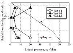
(*3)One of the most important point in conducting this model test in a
centrifuge is that centrifuge modeling is capable to reduce the capillary
rise 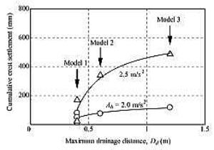 accordingly. In a small scale 1g model test, model embankment will be fully
saturated although the ground water table is at the level of levee base.
A hole of the levee soil may liquefy during shaking test.
accordingly. In a small scale 1g model test, model embankment will be fully
saturated although the ground water table is at the level of levee base.
A hole of the levee soil may liquefy during shaking test.
(*4)It is common in the practice of liquefaction assessment to assume the undrained condition. In the specifications of Japan Road Association, thin liquefiable layers are neglected. The issue of liquefaction of river levees, however, deals with thin liquefiable layer and partially drainage condition may not be negligible.
Assessment method
Okamura & Hayashi (2014),Okamura & Nelson(2016)
Verification of current assessment method
 In order to assess vulnerability to liquefaction of levees, the validity
of the evaluation method of in-situ liquefaction susceptibility is important.
The liquefaction evaluation method used in the current practice is examined.
In order to assess vulnerability to liquefaction of levees, the validity
of the evaluation method of in-situ liquefaction susceptibility is important.
The liquefaction evaluation method used in the current practice is examined.
We picked out 18 severely damaged levees by 2011 EQ. where liquefaction of soils inside the levees are considered as a main cause of damage and 12 undamaged levees in the neighborhood of those damaged levees.
The safety factors against liquefaction, FL (=RL / L), of all the 30 levees
were calculated with the method of the Japan Road Association. SPT-N values
and fines content obtained at the sites after the earthquake were used
to estimate  the liquefaction resistance of the soils, RL.
Cyclic stress ratio developed at the sites, L, were estimated using maximum
ground accelerations at each levee invoked based on those estimated by
the National Institute for Land and Infrastructure Man-agement (EDPD, 2012).
It is of interest to note that the factors FL lower than unity are inevitable
for cases of such a sever event with peak accelerations higher than 300
gals, those 12 levees survived without any noticeable damage. The factors
of safety are not a good index to distin-guish damaged levees from non-damaged
levees. A possible explanation to the fact may be that the soils in the
saturated zones of  those levees did not liquefy probably because generated excess pore pressures
dissipated swiftly during earthquake owing to shorter drainage distances
and higher permeability of soils.
those levees did not liquefy probably because generated excess pore pressures
dissipated swiftly during earthquake owing to shorter drainage distances
and higher permeability of soils.
We, therefore, conducted a series of centrifuge tests to investigate how the drainage during shaking affects pore pressure responses and accelerations  needed to liquefy relatively thin sand layers.
Tests were repeatedly conducted on thin sand layers to investigate effects
on shaking acceleration necessary to liquefy the layers of factors including
relative density and permeability of sand and overburden pressures. It
was found that the apparent liquefaction resistance ratio increased uniquely
with the volumetric strain due to the drainage during shaking until liquefaction
condition  was reached.
Liquefaction assessment with the effects of drainage taken into account was conducted for the damaged and undamaged levees by the 2011 earth-quake. Results of assessment was much improved by considering the drainage effect. Factors of safety stayed lower than unity for all the damaged levees while factors were higher than unity for more than half of the undamaged levees.
Countermeasure
Reference list
Mitsu Okamura and Shuji Tamamura (2011): Seismic stability of embankment on soft soil deposit, Int. J. Physical Modelling in Geotechnics, Vol. 11, No. 2, pp. 1-8.
Mitsu Okamura, Shuji Tamamura and Rikuto Yamamoto (2013): Seismic stability
of embankment subjected to pre-deformation due to foundation consolidation.
Soils and Foundations, Vol. 53, No. 1, pp. 11-22.
M. Okamura and S. Hayashi (2014): Damage to river levees by the 2011 Off
the Pacific Coast Tohoku earthquake and prediction of liquefaction in levees,
Geotechnics for Catastrophic Flooding Events -Iai (Ed) Taylor & Francis
Group, ISBN 978-1-138-02709-1, pp. 57- 67
M. Okamura and F.C. Nelson (2015): Liquefaction assessment of thin sand
layers with partially drained condition, Proc. 6th International Conference
on Earthquake Geotechnical Engineering